
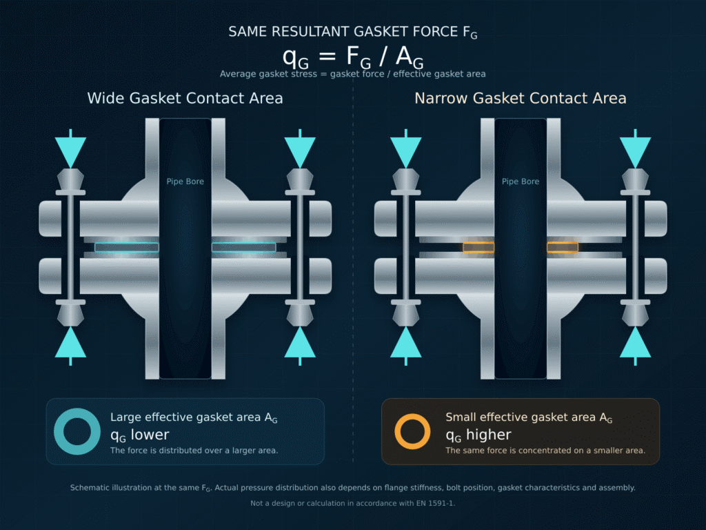
More contact area. More safety. Better sealing? Not necessarily.
At the same bolt load, a wider gasket distributes the available force over a larger area. This reduces gasket stress. Yet this stress is exactly what allows the gasket to conform to the flange surface and close microscopic leakage paths.
The physical principle:
The mechanical relationship pressure equals force divided by area is well known. The same principle can be applied to average gasket stress:
q G = F G / A G
Gasket stress = gasket force / effective gasket area
Here, qG is not the pressure of the process medium inside the pipe. It is the average compressive stress between the gasket and the flange. FG is the force acting on the gasket and AG is the effective gasket area.
If FG remains unchanged, a larger area produces lower average gasket stress.
Reducing the area increases the stress. This can help the gasket conform more effectively to flange roughness and irregularities and close potential leakage paths.
The equation describes an average value. In an actual flange joint, pressure is not distributed uniformly. Flange stiffness, bolt position, flange rotation, gasket characteristics and the tightening sequence all affect the real distribution.
A simple calculation example
In this simplified example, a wide gasket has an effective area of 20,000 mm². A narrower version has an effective area of 10,000 mm². The same gasket force of 400 kN acts on both.
Wide gasket area: 400,000 N / 20,000 mm² = 20 MPa
Narrow gasket area: 400,000 N / 10,000 mm² = 40 MPa
Halving the effective area doubles the average gasket stress in this schematic comparison. To achieve 40 MPa across the wide area as well, the joint would require 800 kN instead of 400 kN.
A reduced gasket area can therefore lower the required bolt load. If the bolts, friction, lubrication and assembly method remain unchanged, this may also allow a lower tightening torque. Torque and bolt load are not the same, however. Torque is only an indirect assembly value and is strongly influenced by friction.
Why an excessively wide gasket is often a disadvantage
The available bolt load in a flange joint is limited. If it is distributed over a very large gasket area, the minimum stress needed for sealing may not be reached. The gasket may appear to contact the flange over a large area without providing reliable tightness.
- A wide area requires more total force to achieve the same gasket stress.
- When bolt load is limited, flange roughness and fine leakage paths may not beclosed sufficiently.
- A large theoretical contact area does not automatically become a uniformlyeffective sealing area.
This is why metallic gaskets often use deliberately reduced contact areas, grooves, serrations or line contacts. The smaller area creates concentric zones of high gasket stress and improves sealability when the total available load is limited.
When a wide or full-face gasket offers advantages
Wider is not inherently wrong. Full-face gaskets are commonly used with flat-face flanges made from comparatively fragile materials such as cast iron or plastic. Full contact can distribute loads more favourably, reduce local bending stress and limit excessive flange rotation.
A full-face gasket also covers the complete flange face. In a properly engineered system, this can limit the ingress of foreign material, shield otherwise exposed areas or form part of a corrosion-control and electrical-isolation concept. Coverage alone does not guarantee corrosion protection. Material compatibility, moisture, the process medium and the overall design must also be considered.
The correct question is therefore not whether the gasket should be as wide or as narrow as possible. The relevant question is which area is effective and safe for the flange, the available bolt load, the gasket material and the actual operating conditions.
What EN 1591-1 actually considers
EN 1591-1 evaluates bolted circular flange joints for mechanical integrity and leak tightness. Effective gasket dimensions and the resulting gasket forces are part of the method. Gasket width is therefore not simply ignored by the calculation.
An additional benefit of full-face coverage, such as shielding external areas from environmental exposure, is not a separate tightness criterion in EN 1591-1. CEN/TR 1591-5 provides supplementary guidance for calculating full-face gasketed joints based on the EN 1591-1 method.
The principle that less area creates more gasket stress remains physically correct. It is not a universal design rule and does not replace a calculation. Only an assessment of the complete joint can confirm whether the bolts, flange and gasket operate within an adequate and permissible load window.
The upper limit: maximum gasket stress
The gasket area cannot be reduced indefinitely. As the area decreases, the risk of overload rises together with the desired gasket stress. The gasket may be crushed, intrude into the pipe bore or lose its recovery. The flange and bolts also impose limits.
The gasket parameters determined according to EN 13555 describe this operating window:
- Q (L) is the minimum assembly gasket stress required for the specified tightness min
class.
- Q (L) is the minimum stress required in service after unloading and at smin
temperature.
- Q is the maximum permissible stress at the relevant temperature before the smax
gasket is damaged.
A reliable design lies between these limits and also considers relaxation, temperature, flange surface condition and assembly scatter. The objective is not the smallest possible area, but a load-efficient area with an adequate safety margin.
How revoseal JP applies the principle
The revoseal JP applies area reduction through a controlled gasket geometry. Metallic inner and outer teeth concentrate sealing action on very narrow concentric contact zones. This creates high local gasket stress even at comparatively low bolt loads.
The higher inner and outer teeth encapsulate the graphite or PTFE overlay. The tooth geometry controls compression of the facing and creates an additional metallic seal. This combines the conformability of a soft facing with defined metallic sealing lines.
Graphite does more than act as a filler. It conforms to roughness, closes microscopic leakage paths and supports the metallic profile during controlled compression. The design can therefore use high local stress without subjecting the flange face to an uncontrolled, unsupported sharp contact. Correct material selection and an application-specific calculation remain essential.
Conclusion: less area can mean better sealing
A wider gasket distributes force. This can be beneficial by design, but at the same total force it reduces average gasket stress. A narrower, carefully engineered sealing area can therefore provide better tightness while reducing the required bolt load and tightening torque.
The permissible range is determined by the gasket, flange and bolts together. Minimum and maximum gasket stress must be considered alongside temperature, medium, flange surface condition and assembly quality.
Are you dealing with a flange joint that has limited bolt load, an unusually wide gasket area or recurring leakage? Revoseal can support gasket selection, joint design and the calculation of a load-efficient sealing solution.